プロジェクト概要
Project Overview
ある航空宇宙関連企業様が、金属AMで製造する熱交換器のR&Dプロジェクトに取り組んでおられるのですが、本案件では多数の形状バリエーションを持つ3Dモデル群を自動生成するためのプログラムを開発・納品いたしました。
For an aerospace company, we developed and delivered a program that automatically generates the 3D models with enormous variations of geometry for their R&D project about heat exchanger manufactured with metal AM.
本プロジェクトのキーワード
分野:航空宇宙、熱交換器
造形技術:金属AM
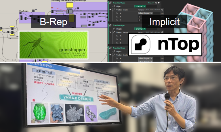
ソフトウェア:Grasshopper (B-Rep), nTop (implicit modeling)
その他:自動設計, Computational Design, 自己交差
Keywords in this project
Domain: Aerospace, Heat Exchanger
3D Printing Technology: Metal AM
Software: Grasshopper (B-Rep), nTop (implicit modeling)
Others: Auto-designing, Computational Design, Self-intersectioning
多数のトレードオフ要素
Many trade-off factors
熱交換器には業界・用途ごとに多様な種類が存在します。いずれの種類においても、設計の際は下記4つの要素が重要とされています。
There are various types of heat exchanger for target usage and industries. Regardless of the type, the following 4 factors are important in the design process.
- 伝熱性能/Heat Transfer Performance
- 圧力損失/Pressure Drop
- 構造強度/Structural Strength
- 重量/Weight
特に航空機に搭載される熱交換器では、4つの要素すべてがトレードオフ関係にあるため、必要要件を満足しつつ全要素の良好なバランスを維持するには非常に高度な技術力が必要です。
Especially for heat exchangers installed on aircraft, all of 4 factors are in a trade-off relationship. Therefore, highly advanced engineering capability is required to maintain a good balance across all factors while satisfying the requirements from the end customer.
お客様の課題:膨大な数の3Dモデル群
Client’s challenge: A vast number of 3D models
The image above is not related to the actual project
複数のパラメータを様々に変化させて膨大な数のバリエーションをもつ3Dモデル群を作成し、それらを金属3Dプリント技術で実際に造形するのですが、「どうやって膨大な数の3Dモデリング作業を行うのか」が課題でした。一般的な3D-CADで一つ一つ手作業でモデリングするのは非効率的だからです。
The client needed to prepare 3D models with a vast number of variations on geometry by changing the multiple parameters. “But how to do it?” That was the client’s challenge because it is not efficient to create 3D model manually one-by-one using conventional 3D-CAD.
解決策:自動設計(Computational Design)
Solution: Computational Design
そこで本案件では、一般的な3D-CADの代わりに「Computational Design」と呼ばれる手法を採用しました。これは、まずプログラム(アルゴリズム)を作成し、次に変数パラメータを変更して膨大な数のバリエーションをもつ3Dモデル群を自動生成させる手法です。
In this project, we used an approach called “Computational Design” instead of conventional 3D CAD. We developed a program (algorithm), then change the variable parameters to automatically generate a vast number of 3D model variations.
複数ソフトを使い分け
Combination of multiple software
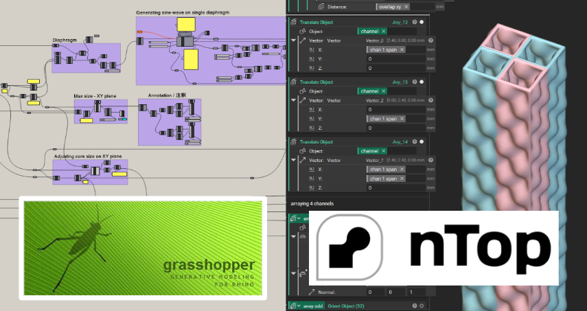
本案件では、プログラムで3Dモデリングするためのツールとして2つのソフトウェア、GrasshopperとnTopを使用しました。
In this project, we used Grasshopper and nTop as tools for 3D modeling by programming.
各ソフトの特性
Characteristics of each software
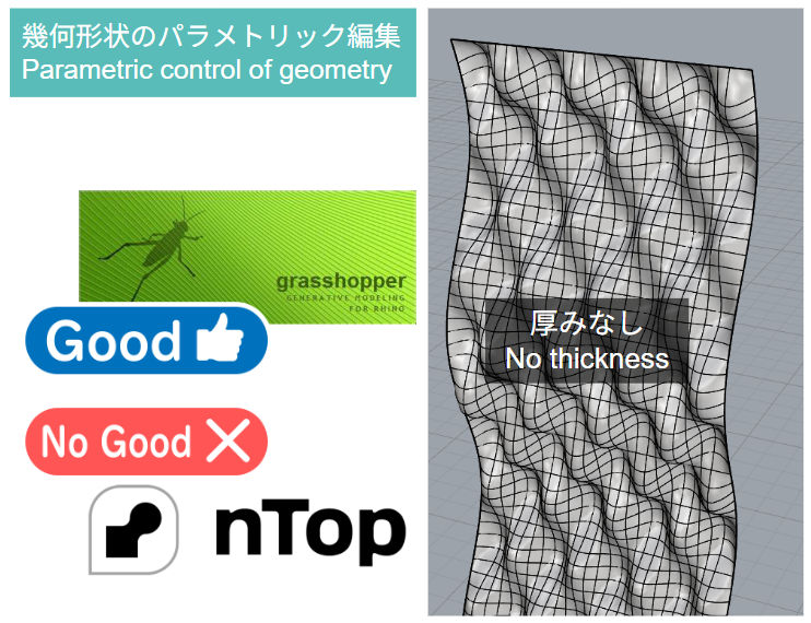
幾何形状のパラメトリック編集
Parametric control of geometry
例えば下図のような幾何形状をプログラミングで3Dモデリングし複数の変数を変更してパラメトリックに編集する場合、Grasshopperを用いると取り組みやすいですが、nTopでは取り組みづらいです。
For example, when creating a geomety shown below through programming and editing it parametrically by changing variables, it is easy for Grasshopper but tough for nTop.
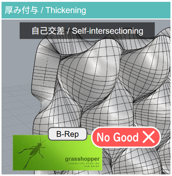
厚み付与 ⇒ 自己交差
Thickening ⇒ Self-intersectioning
次に、上図の幾何形状に厚みを付与する場合、Grasshopperを用いると下図のように自己交差が発生し後続のモデリング工程がスムーズに進行できなくなります。これがGrasshopper (B-Rep) の難点です。したがって、Grasshopperのみで本案件を遂行するのは非常に困難です。
Next, when thickening the geometry shown above, it is tough with Grasshopper due to “Self-intersectioning” as shown below and this problem will be critical barrier in the subsequent modeling steps. Therefore, it is very difficult to proceed this project with Grasshopper solely.
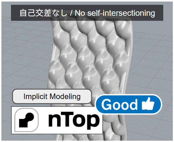
自己交差を回避
Avoiding Self-intersectioning
一方、nTop (implicit modeling) では原理的に自己交差が発生しないので、厚みを付与する操作やそれ以降のモデリングがスムーズに進行します(下図)。
On the other hand, nTop (implicit modeling) can proceed the thickening operation on the geometry without any problem as shown below because there is no concept of self-intersectioning inherently in the theory of implicit modeling.
以上のような各ソフトの特性の差異から、本案件では全工程のうち前半にGrasshopper (B-Rep)を、後半にnTop (Implicit modeling)を採用することにしました。
Considering the differences in characteristics mentioned above, we decided to use Grasshopper (B-Rep) for the first half of the entire process and nTop (Implicit modeling) for the latter half in this project.
自動設計プログラムの機能
Features of the program for auto-designing
流路コア
Fluid Channel Core
まず全体エリアのサイズを指定します。次に流路1本のサイズを変更すると、それに伴い全体エリア内にうまく収まるよう流路の本数が自動的に調整、配置されます。
First, designate the size of overall area. Next, when you change the size of a single fluid channel, the count of channel will be automatically adjusted and arrayed within the designated over all area.
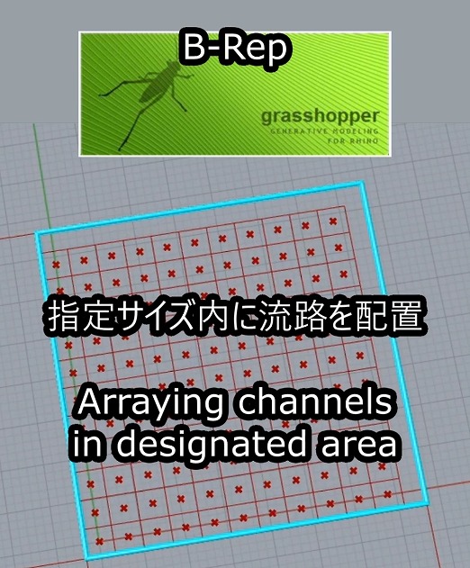
Arraying the fluid channels in designated area
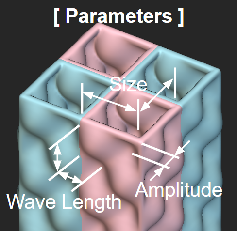
流路の隔壁形状の編集(厚みなし): Sine波における波長、周期、振幅の数値を調整し、隔壁の姿を見ながら編集できます。このような幾何形状をパラメトリックに編集するにはGrassshopperが向いています。nTopはこのような操作が不向きです。
Editing the diaphragm of fluid channel (no thickness): Adjust the wavelength, cycle and amplitude values of the sine wave while viewing the geometry. Grasshopper is suited for parametric editing of this type of geometries but nTop is not well-suited.
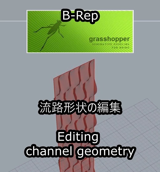
Editing the channel geometry
シミュレーション機能:流路をコア全域に配置した際の全体像を視覚的に確認できます。
Simulation feature: Displays an overall view when all the fluid channels are layouted in entire area of core.
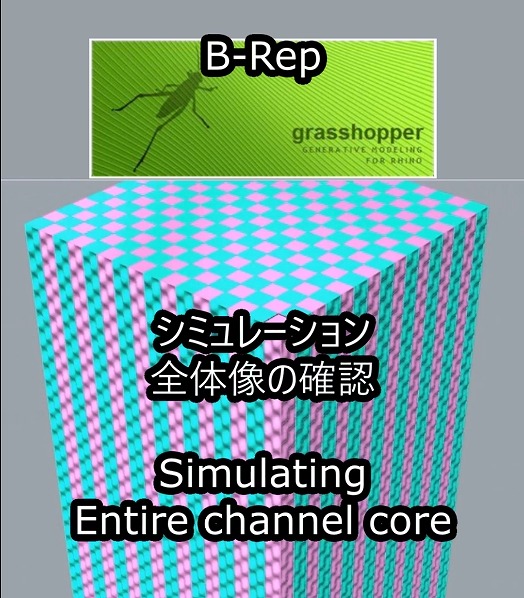
Simulation: Entire channel core
ここから先はnTopを使用します。Grasshopperからエクスポートした流路形状をnTopにインポートし厚み付けします。もしこの操作をGrasshopper上で実行すると、代入値によっては自己交差が発生するケースがあります。一方nTopでは原理的に自己交差が発生しません。
From here on, nTop is used. Import the fluid channel geometry exported from Grasshopper into nTop and thicken it. If this operation is performed within Grasshopper, self-intersections may occur depending on the input values. In contrast, self-intersections never occur in nTop inherently.
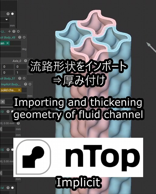
Importing and thickening the geometry of fluid channel to nTop
流路コア完成:自動的に流路形状がコア全域に配置され完成です。
Completion of fluid channel core: All fluid channels are layouted on entire area of core.
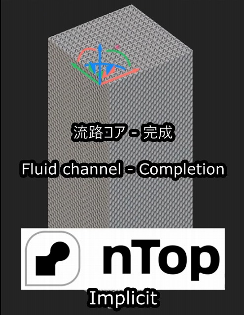
Fluid channel – Completion
分配部
Distributor
基本要素のサイズ調整:このGrasshopperプログラムでは幾何形状の設計ルールがアルゴリスム化されています。流路1本のサイズを変更すると、設計ルールに則って基本要素の幾何形状が自動的にモデリングされます。またシミュレーション機能を用いて、複数の基本要素を配置した場合の様子を表示し視覚的に確認する事ができます。(諸事情により画像にモザイク加工を施しております)
Adjusting the size of unit cell: The design rule for geometry of unit cell is described as algorithm in this Grasshopper program. When you change the size of a single fluid channel, the algorithm automatically generates the entire geometry of unit cell. Also, the program has a simulation feature allowing you to check the view when the multiple unit cells are layouted. (The image is pixelated.)
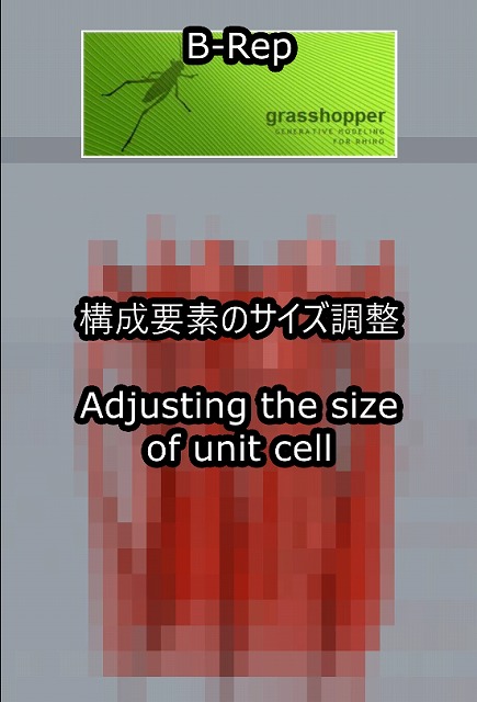
Adjusting the size of unit cell
分配部 完成:ここから先はnTopを使用します。Grasshopperからエクスポートした基本要素形状をnTopにインポートし、アルゴリズムが設計ルールに従って自動的に配置し全体像を生成します。(諸事情により画像にモザイク加工を施しております)
Completion of distributor: From here on, nTop is used. Import the geometry of unit cell exported from Grasshopper into nTop and then the algorithm automatically arrays them and generates the entire structure of distributor. (The image is pixelated.)
Auto-generating the entire distributor
設計業務の自動化:お話をお聞かせ下さい
We help you automate your design workflow
「多数の3Dモデルを作成する必要があるが、一般的な3D-CADでは困難。3Dモデリング作業を自動化してプロジェクトの進捗をスピードアップしたい。」「多様な基本形状に対し同一の編集プロセスを施すマスカスタマイゼーションに取り組みたい。」こんなご要望をお持ちの皆様をご支援いたします。プロジェクトの構想をお聞かせ下さい。Computational Design(自動設計)の手法を用いると、設計業務を大幅に効率アップできるかも知れません。
Struggling to create a vast number of 3D models using normal 3D-CAD? Planning to launch a mass-customization service where applying the designated editing process to various base geometries? Let us hear about your project. You can improve the efficiency of your design work flow by “Computational Design (Auto-design).”